| substrate |
Commonly used materials include FR-4 (glass fiber epoxy resin), high-frequency materials (Rogers, PTFE), and flexible substrates (PI). |
| conductive layer |
Copper foil (electrolytic copper/rolled copper) typically has a thickness of 0.5oz to 3oz (18μm to 105μm). |
| Line width/line spacing |
Standard designs have a thickness of ≥0.1mm, while high-density fiberboard (HDI) can reach 0.05mm or even thinner. |
| Impedance control |
For high-frequency signals, it is necessary to calculate the line width, dielectric thickness, and dielectric constant (such as 50Ω/100Ω differential lines). |
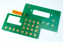
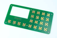
| Surface treatment |
Immersion gold (ENIG), HASL (HASL), OSP (anti-oxidation), and hard gold plating (wear-resistant). |